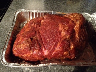
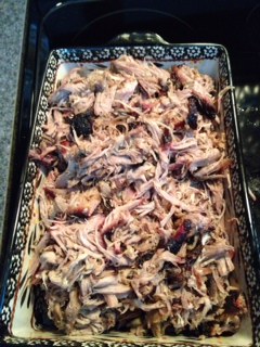
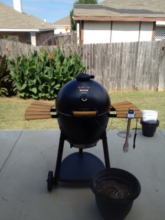
 I have recently started getting into smoking my own BBQ at home using a Char-Griller Akorn kamado grill. The grill itself and food coming off of it has been awesome so far (cooked a low and slow pork butt that went for 12 hours and a turkey that went for 4+). But one of the challenges of making really good smoked BBQ is getting the temperature of the grill to sit right where you want it (say 225 degrees) over long periods of time and in some cases this mean going all night (which I did with the pork butt). Kamado style smokers are very good at this consistency, but in many cases (esp. with a lower priced model like the Akorn) you are going to need to baby sit it a bit and watch for drops and rises in temperature so that adjustments can be manually made. Even with a good remote monitor like the Maverick and a well insulated cooker it can lead to long nights of adjusting the dampers to maintain temps.
A solution to this problem are BBQ pit temperature controllers. These devices act like a thermostat for a BBQ and control the flow of oxygen to the fire in order to raise (stoke) or lower (dampen) it. Most use a hardware / software system called a PID Controler (proportional-integral-derivative controller). This controller measures the current temperature of the pit and based on time, last reading, etc. decides if the fire needs more or less oxygen. If more oxygen is needed the device turns on a small blower that is attached to the grill (in the case of the Akorn at the bottom damper slot). It is important to note that the grill needs to be pretty air tight (if at all possible) in order to get the best results out of this sort of system, otherwise outside air will “leak” in and stoke the fire.
There are quite a few off the shelf commercial solutions out there that can be purchased based on PID technology. The lower cost models (~$150) like the Auber or Party Q are basically just a PID controller and a blower. While the more expensive models ($300+) like the Cyber Q and Rock’s Stoker include more advanced capabilities like WI-FI network access and built in web servers for remote monitoring and operation. Some of the more expensive models also offer more temperature probes for food (most have just 1 pit probe and 1 food probe). Of course, being the tech geek I am, I really wanted one of the network enabled models but the cost was more than my grill! Luckily I found what turned out to be the solution, an open source project called Heatermeter!
Now, let me start out by saying, this is not for the feint of heart. There is low level electronics work involved here including soldering onto a Printed Circuit Board (PCB) of lots of little parts. But, if you can follow some pretty simple instructions, and watch lots of videos on YouTube about soldering… you can build this thing and get the capabilities of the more expensive products for the price of the cheaper ones. If I can do it so can you! Ok, so what the heck is a Heatermeter?
Basically you take a Raspberry Pi (tiny linux computer), a specialized PCB that all of the electronics components go onto including an ATmega328P microcontroller (also used in the Arduino), and a software image the good folks at the Heatermeter project put together and you have the beginnings of a web enabled BBQ pit controller! All you need then is a blower (that you have to do a little surgery on), some temperature probes (you can use the ones from a Maverick temperature monitor), something to put it all in (they have designs for 3d printed cases, which is what I have but any old project box or even Tupperware would work) and a way to power the device (can use USB or an external 12V wall wart power adapter). Oh and by the way it works awesome!
I will not go into all of the ins and outs of assembly and parts as all of that is covered in the official project wiki with further information available on a message board. But I will post a couple of pics of my handy work below and describe a few things.
This first image shows the Heatermeter PCB with a few resistors added to it but not yet soldered in place. The assembly of the Heatermeter requires only pass through components. In fact the only surface mount component is an optional wireless module if you are trying to use wireless temperature probes which I did not need.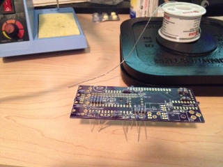 There really is not anything special about the assembly beyond what you would find in any electronics project other than the main button (which is actually a four way joystick like button) and the three LED lights need to be positioned at an appropriate height off of the PCB if fitting into a 3d printed case. I did a pretty good job on the button, but mounted my LEDs a bit too high, so they stick out of the case a bit.
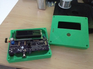
The next pic shows the fully assembled device with the Raspberry Pi joined to it. The RP connects to the Heatermeter using the GPIO pins on the Pi.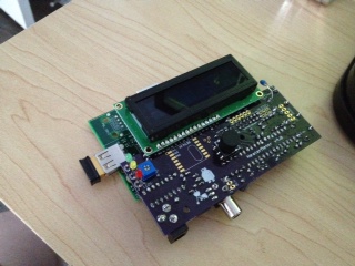 I would like to point a couple of things out here: First, at the very top of the device you can see the LCD screen. This screen allows the device to be used without going through the web interface and can be controlled with the center joystick button just below it. To the left of the screen you can see the Raspberry Pi’s USB slot and the USB WI-FI dongle plugged in. I was able to set mine up to a static IP so that it could be accessed from outside of my network if needed via port forwarding from my router. Next, at the bottom of the device you can see the barrel plug on the left (this is for 12v power) and the RCA jack near the center. The RCA jack is interesting as it is what supplies power as needed to the blower. I had to take off the power jack from the Auber blower I purchased and solder an old RCA connector in its place. Works well, but is just a little strange. Lastly, on the right side of the device (which you cannot see from the pic) are the four jacks for the temperature probes. The bottom jack is for the BBQ pit and the other three are for food items. Each probe can have individual alarms set for both high and low temperature and scripts can be written to do things like sending an email when an alarm happens.
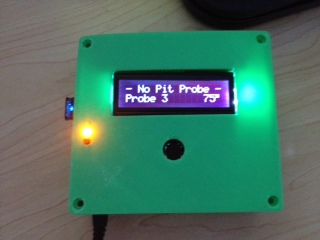
The next two pics show off the device sitting in the 3d printed case with the last one showing what it looks like when running. You can also see the 12v power applied at the bottom.
Finally, a pic of the web interface. The interface shows the BBQ pit temperature and set point (the desired temp) at the top with each probes readings below. The probes can be labeled in the interface and changes made to the set point right from this main screen. Additional setup is available from the web configuration screens including alarms, scripts, and network setup. Also, the graphs are a really nice feature, and the interface continuously updates without intervention.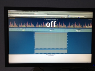
In conclusion, I absolutely LOVE this thing. It was fun to build (and I only burnt myself once on the soldering iron). If you are looking for a networked PID based BBQ temperature controller and are not afraid of an electronics project I highly recommend trying it out. The community surrounding the project is really great too so check out the message board I linked earlier in the post.
Good cookin!